
General Research interests
• Ultrafast photonics;
• Optical signal processing;
• Optical pulse shaping;
• High-speed signal characterization and measurement;
• Fourier optics and imaging;
• All-fiber technologies;
• Integrated waveguide devices;
• Silicon photonics;
• Fiber/waveguide Bragg and long-period gratings;
• Optical telecommunications;
• Optical computing;
• Ultrafast information processing;
• Light interferometry;
• Microwave photonics;
• Ultra-broadband microwave engineering.
Overview of scientific contributions and ongoing research activities
(For each of the listed items, some samples of relevant recent contributions are provided and described in more detail)
•Proposal and demonstration of innovative methods for time-domain optical signal processing using all-fiber and integrated-waveguide devices, particularly fiber/waveguide gratings, including pulse repetition rate multiplication, ultrafast photonic temporal differentiation and integration, real-time optical Hilbert transformation, and picosecond and femtosecond optical pulse shaping.

The implementation of all-optical circuits for computing, information processing, and networking could overcome the severe speed limitations currently imposed by electronic-based systems. A promising approach toward the implementation of ultrafast all-optical circuits is to emulate the developments in the electronic domain, i.e., to follow similar component and design strategies, using photonic technologies. For this purpose, basic building blocks for high-speed analog optical signal processing need to be developed, including optical differentiators, integrators, Fourier transformers and Hilbert transformers. Such developments have recently attracted an increasing interest for optical communications, pulse shaping or sensing applications that use optical signals.
An all-optical temporal differentiator is a fundamental function for ultrafast signal processing, which provides the derivative of the time-domain complex envelope of an arbitrary input optical signal. In general, an all-optical temporal differentiator can be realized using a linear optical device that has a spectral transfer function proportional to the term (ω-ω0)N, where N is the differentiation order, ω is the optical frequency variable and ω0 is the optical carrier frequency of the optical signal to be processed. This functionality can be implemented using a linear optical filter providing a linear amplitude (V-shaped) spectral response over its operation bandwidth with a complex zero at the carrier frequency of the signal under test. All-optical differentiators have been designed and demonstrated with operation bandwidths up to a few THz by use of an integrated-optic transversal filter approach, fiber gratings, silicon ring resonator and Mach-Zehnder interferometers.
We have recently proposed and experimentally realized a novel ultra-broadband all-optical differentiator scheme based on a simple and widely available technology, namely a wavelength-selective directional coupler made of non-identical waveguides in an integrated-waveguide or optical fiber structure. The distinctive feature of the differentiator based on a directional coupler is that it can offer an extremely broad bandwidth, ~25 THz in our experimental demonstrations, a world record operation bandwidth.

Figure: (a) Schematic diagram of the wavelength-selective directional coupler used for ultrafast optical differentiation; (b) Measured and simulated spectral magnitude and phase response; (c) Experimental setup for characterization. (d) Experimental results of optical temporal differentiation and flat-top pulse shaping by shifting the wavelength of an input Gaussian-like optical pulse with respect to the resonance of the differentiator.
[1] M. Li, H.-S. Jeong,J. Azaña, and T.-J. Ahn, “25-terahertz-bandwidth all-optical temporal differentiator,” Optics Express 20, 28273–28280 (2012).

All-optical analog circuits for computing, information processing and networking could overcome the severe speed (i.e., bandwidth) limitations presently imposed by the use of electronics. However, in photonics, there are very few fundamental ‘building blocks’ equivalent to those used in electronics (e.g. differentiators, integrators, memory elements etc.) to build up complex circuits for advanced analysis, processing and computation. Realizing these photonic building blocks in a monolithic platform – ideally compatible with CMOS technology – represents a crucial step for the future development of ultrafast computing and information processing circuits on a chip. Our group has pioneered worldwide the design and experimental realization of several key basic ‘building blocks’ for ultrafast analog optical signal processing, most prominently, optical temporal differentiators and integrators, real-time optical Fourier and Hilbert transformers etc. As a very relevant example, we reported the first monolithic photonic integrator based on a passive micro-ring resonator in a CMOS compatible platform, performing an unprecedented time-bandwidth product of ~100 (~200 GHz processing bandwidth and ~800 ps integration time window), shown in [1]:
Plot (a) shows a schematic of the used integrated micro-ring resonator device, illustrating its working principle as a photonic temporal integrator. In the plots (b), (c), and (d), the input/output system time-domain response is represented. More specifically, the cumulative time integral has been performed on different waveforms: i) the optical pulse directly generated by the laser source (b, inset-2); ii) a sequence of two pi-shifted pulses with a temporal delay of 275 ps (c, inset); and iii) a strongly chirped optical pulse with a field-amplitude time duration around 1,340 ps, corresponding to an intensity time-width of ~800 ps (d, inset). This latter pulse was generated by propagation of the original laser pulse through a highly dispersive chirped fiber Bragg grating (FBG). The corresponding experimental (black curve) and theoretical (red curve) time integrals are represented in the main plots. Inset b-2) depicts the experimental impulse response obtained by using a fast (~8 ps) amplified photo-detector.

[1] M. Ferrera, Y. Park, L. Razzari, B. E. Little, S. T. Chu, R. Morandotti, D. J. Moss, J. Azaña, “On-chip CMOS compatible all-optical integrator,” Nature Commun. 1:29 doi: 10.1038/ncomms1028 (2010).
• Fundamental studies on space-time duality theory (e.g. time-lens concept) and proposal and demonstration of novel optical pulse processing techniques based on this theory, including temporal self-imaging (Talbot) phenomena (on periodic optical pulse trains), real-time Fourier transformation (frequency-to-time mapping), simplified ‘temporal imaging’, temporal zone plates for short pulse generation, and the concept of time-domain holography.

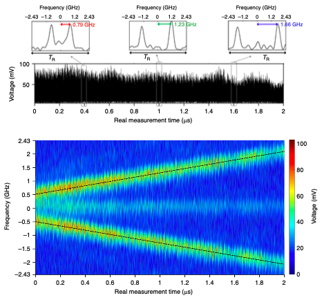
Real-time Fourier transformation (RTFT) enables Fourier analysis at speeds beyond conventional digital signal processing. Optical RTFT commonly relies on mapping the spectrum of the waveform under test to the time domain by inducing large amounts of group velocity dispersion, see for instance pioneering work in IEEE J. Quantum Electron. 36, 517-526 (2000). However, the relatively limited dispersion of commonly-available transparent media limits the typical optical frequency resolution of RTFT to above the GHz range. This represents a critical limitation for applications in real-time spectroscopy, ultrafast detection, imaging and sensing, as well as photonic-assisted generation and processing of radio-frequency (RF) signals.
We have recently proposed an RTFT concept that extends the resolution of RTFT analysis to the kHz regime, by avoiding the use of dispersion altogether. The concept is based on the superposition of multiple input signal replicas, which shift simultaneously along the time and frequency domains in a frequency-shifted feedback (FSF) loop.
Under the scheme depicted in Fig. (a), an input signal photon circulates in the FSF loop with a round-trip time τc; on each round trip, an acousto-optical frequency shifter (AOFS) shifts the photon’s frequency by fs. An intra-cavity bandpass filter and amplifier controls the number of round trips in the loop. Assuming that the product of the round-trip time and frequency shift equals an integer (p = 1, 2, 3, …), the shape of the output time trace reproduces the optical spectrum profile of the input. The inverse of a photon’s total lifetime in the loop gives the technique’s frequency resolution. Fig. (b) shows the obtained RTFT time traces of a continuous-wave laser modulated with a single radio-frequency tone of frequency fm. Fig. (c) compares the input spectrum under analysis with the obtained time trace (fm = 200 kHz).
We have demonstrated successful RTFT of optical signals with a frequency resolution as high as about 30 kHz, and a time-bandwidth product higher than 400 –results that exceed dispersion-based schemes by orders of magnitude. The processing architecture features minimal latency (equal to the inverse of the frequency resolution) and, contrary to other schemes, the method requires neither truncated nor coherent input light. This concept opens new perspectives in optical real-time Fourier analysis, with applications beyond our optical-domain implementation.

[1] H. Guillet de Chatellus, L. Romero Cortés, and J. Azaña, “Optical real-time Fourier transformation with kilohertz resolutions,” Optica 3, 1-8 (2016).

•Proposal and demonstration of a universal method for passive (noiseless) amplification and real-time averaging of repetitive signals involving temporal phase modulation and dispersive phase filtering. •Proposal and realization of novel photonic temporal/spectral signal processing methods based on time-frequency optical dualities, including time-to-frequency conversion, spectral self-imaging phenomena (on periodic optical frequency combs) and frequency-domain Talbot array illuminators. This latest technique has been used for demonstration of a new invisibility concept, the spectral invisibility cloak. •Fundamental studies, proposal and demonstration of innovative high-speed signal processing technologies based on space-time and time-frequency dualities using broadband incoherent light sources.Our group introduced the concept of time-domain holography as the temporal equivalent of the well-known process of spatial-domain holography, a feat that represents a new milestone within the context of the so-called space-time duality. Time-domain holography involves two main steps, respectively equivalent to the signal recording stage and the signal retrieval stage (Fig. 1). In the signal recording stage, an interferogram is created by inserting the time-domain information signal and a reference monochromatic wave (CW signal) in a heterodyne detection configuration using a single photodector. Alternatively, the modulating interferogram signal can be also computationally designed for generation of a desired, user-defined optical complex waveform using the described single intensity-modulation scheme. This latest process can be interpreted as the time-domain counterpart of Computer Generated Holography (CGH, Fig. 1(a)). In the signal retrieval stage, the optical complex waveform is created by inserting the previously detected temporal hologram (or the computationally generated hologram created using an arbitrary waveform generator) as a signal modulating the temporal waveform of another CW light source, e.g., using electro-optic modulation. At the output of the modulator, several terms can be identified that are spectrally separated, exactly as in the spatial-domain holography problem. One of these terms is an exact copy of the information signal, and can be easily filtered in (selected) using a band-pass optical filter (Fig. 1(b)). There is also an additional term that is the temporal complex conjugate of the input signal – if selected through a complementary band-bass optical filtering process, this would enable a simple way of achieving optical phase conjugation of the input signal, a highly desired signal-processing functionality for many interesting operations.
This novel concept has been experimentally demonstrated through the generation and subsequent retrieval of user-defined, complex optical temporal waveforms using simple schemes based on time-domain equivalents of holographic concepts. In particular, Fig. 2 shows an example of experimentally generated complex optical waveforms using intensity-only temporal modulation, namely, a 1024-symbol 3-Gbps optical data stream under a 16-QAM-modulation format.

[1] M. R. Fernandez, M. Li, J. Azaña, “Time-domain holograms for generation and processing of temporal complex information by intensity-only modulation processes,” Opt. Express, vol. 21, pp. 10314-10323 (2013).
[2] M. R. Fernández-Ruiz, J. Azaña, “Temporal phase conjugation based on time-domain holography,” Opt. Lett., vol. 40, pp. 127-130 (2015).
[3] M. R. Fernández-Ruiz, L. Lei, M. Rochette, J. Azaña. (2015). All-optical wavelength conversion based on time-domain holography. Optics Express. 23(17): 22847-22856.

A time lens is the temporal equivalent of a spatial thin lens, typically implemented through quadratic temporal phase modulation of the waveform under analysis. Related with this concept, a temporal zone plate enables the compression of CW light into short optical pulses through a two-step process, involving temporal modulation (e.g., through an electro-optic modulator driven by an electronic waveform generator) followed by chromatic dispersion. Temporal zone plates do not exhibit the limiting trade-off between temporal aperture and frequency bandwidth (temporal resolution) of conventional linear (electro-optic) time lenses, enabling compression of CW light over a much longer temporal period (time aperture). The latest is of critical importance to achieve higher energy pulses. There are two kinds of temporal zone plates – temporal intensity and phase zone plates, which can be realized by temporal intensity and phase modulation, respectively. As an example, temporal phase zone plates, which are the time-domain analog of spatial phase zone plates, are illustrated in Fig.1.
To demonstrate the introduced temporal zone plate concept, we set up a linear optical pulse compression experiment, in which 1st-order, 2nd-order, and 3rd-order temporal phase zone plates are used. The electronic waveforms, which are used to drive the electro-optic phase modulator, are shown in Fig. 2. The temporal apertures for order 1, 2, and 3, which equal to the temporal duration of the electronic waveforms, are 1.88 ns, 3.85 ns, and 5.77 ns, respectively. The corresponding compressed pulse waveforms are shown in Fig. 3. There is a good agreement between numerical simulation (in which the experimental limitation is considered so that it is slightly deviated from the ideal profile) and experiment. For the cases of order n=1, 2, 3, the FWHM of the compressed temporal pulses in the experiments are 38.6 ps, 23.9 ps, and 25.5 ps, respectively. Thus the time-bandwidth products (ratio of temporal aperture to resolution) for these three experiments are 50, 161, and 226, respectively, significantly surpassing the capabilities of conventional time lenses. For further advancements in optimized temporal zone plate designs, see [2] and [3] below.

Fig. 1. Space-time duality. (a) Light focusing by a spatial phase zone plate. (b) Pulse generation and compression from CW light by a temporal phase zone plate. Fig. 2. Ideal and experimentally measured electronic waveforms for temporal phase modulation in the implemented temporal phase zone plates for orders (a) n=1, (b) n=2, and (c) n=3. Fig. 3 Temporally compressed intensity waveforms in the ideal case, simulation, and experiment using temporal phase zone plates of orders (a) n=1, (b) n=2, and (c) n=3. (d)-(f) show a closer view of the compressed optical pulses in (a)-(c). All waveforms are represented in normalized units.
[1] B. Li, M. Li, S. Lou, and J. Azana, “Linear optical pulse compression based on temporal zone plates,” Optics Express, vol. 21, pp. 16814-16830 (2013).
[2] B. Li, M. R. Fernández-Ruiz, S. Lou, J. Azaña, “High-contrast linear optical pulse compression using a temporal hologram,” Opt. Express, vol. 23, pp. 6833-6845 (2015).
C. R. Fernández-Pousa*, R. Maram*, J. Azaña. (2017). CW-to-pulse conversion using temporal Talbot array illuminators. Optics Letters. 42(13): 2427-2430

Traditional amplifiers employ an external power source to multiply the incoming signal carrier through an active gain process. In addition to amplifying the signal, this process introduces various forms of noise and distortion, such as amplified spontaneous emission noise (ASE), pulse-to-pulse intensity fluctuations, and timing-jitter. In this work, we developed a noiseless passive amplification technique for repetitive waveforms without using active gain [1, 2]. Our technique employs lossless repetition-rate division of the input periodic waveform train through a dispersion-induced self-imaging (Talbot) effect, inherently leading to energy amplification of the input individual waveforms. When inputting a noisy train, this technique can reduce pulse-to-pulse intensity fluctuations and timing-jitter, enhance the pulse extinction ratio, and reduce ASE fluctuations by a desired factor to improve signal quality. In particular, Talbot amplification can reduce ASE noise similar to a real-time averaging process.
Fig. 1(a) illustrates the concept of our passive amplification technique. Application of a prescribed temporal phase-modulation profile [1] to the input periodic pulse train produces new frequency components, and the subsequent dispersion-induced temporal self-imaging effect temporally re-distributes the new spectrum to coherently add the energy of the original repetitive waveforms into fewer identical but amplified waveforms. Fig. 1 (b) shows an experimental sampling oscilloscope time trace for passive amplification of picosecond pulses by a factor m=15.
Figs. 1(c)-(e) show how Talbot amplification behaves as a conventional averaging process, e.g., scope averaging, on ASE-like intensity noise fluctuations. Fig 1(c) shows experimental data for the coefficient of variance (CV), the ratio of the standard deviation to the mean for the top level, of a noisy pulse (OSNR=10) vs. the inverse of the square root of the amplification factor m=N (red squares). Also shown is the CV vs. the inverse of the square root of number of scope averages N (blue circles), demonstrating the equivalence of Talbot amplification to averaging. The theoretical trend line for scope averaging, which scales as √N, is overlaid (dashed green). Experimental sampling oscilloscope traces in Fig. 1(d) and 1(e) show how the point-to-point fluctuation is nearly the same for scope averaging and Talbot amplification. Fig 1(d) shows results for a pulse without passive amplification and a regular scope average of N=15, and Fig. 1(e) shows results for a Talbot-amplified pulse by m=15 with no scope averaging. Passive amplification is therefore equivalent to a real-time optical average. Said another way, Fig 1(e) is the equivalent of Fig 1(d) without the need for detection and post-processing. Such a real-time average could be particularly important where a clean pulse is needed directly in the optical domain. Repetitive waveforms buried under a noise floor have been successfully extracted from the noise using the Talbot passive amplification method [1, 2]. Through a suitable exchange of the temporal phase modulation and dispersive phase filtering stages, the method has been successfully applied to passive noiseless amplification of repetitive waveforms along the frequency domain, i.e., optical frequency combs [3, 4] .

Fig. 1 (a) Passive waveform amplification concept, assuming m = 3. (b) Sampling oscilloscope time traces (input: dashed blue; output: solid red) for amplification factor m=15. (c) Ratio of pulse variance to mean vs. 1/√N, where N = m. (d) and (e) Electrical sampling oscilloscope traces (d) without passive amplification, scope average N=15, (e) m=15 and no scope averaging, for OSNR=10.
[1] R. Maram, J. van Howe, M. Li, and J. Azaña, “Noiseless intensity amplification of repetitive signals by coherent addition using the temporal Talbot effect,” Nat. Commun. 5:5163 doi: 10.1038/ncomms6163 (2014).
[2] R. Maram*, M. Seghilani*, J. Jeon*, X.-Z. Li*, L. Romero Cortés*, J. van Howe, J. Azaña. (2018). Demonstration of input-to-output gain and temporal noise mitigation in a Talbot amplifier. IEEE Photonics Technology Letters. 30(8): 665-668.
[3] L. Romero Cortés, R. Maram, H. Guillet de Chatellus, J. Azaña. (2018). Subnoise detection and passive amplification of frequency combs through customized coherent spectral energy redistribution. Physical Review Applied. 9: 064017-(1-7)
[4] L. Romero Cortés, R. Maram, H. Guillet de Chatellus, J. Azaña. (2019). Arbitrary energy-preserving control of optical pulse trains and frequency combs through generalized Talbot effects. Laser and Photonics Review. 13: article #1900176.
The last decade has seen the emergence of numerous methods to conceal objects by preventing light from interacting with them. This is known as invisibility cloaking, and solutions have been demonstrated over different regions of the electromagnetic spectrum, and even for waves of very different nature, including acoustic and thermal waves. While effective invisibility solutions have been demonstrated for single- frequency illumination waves, realistic operation conditions require cloaks capable of concealing objects from broadband illumination.
An ideal cloak must restore the exact amplitude and phase distributions of the illumination wave–the full field–at its output. However, current invisibility strategies rely on altering the propagation path of the wave around the object to be concealed. By fundamental operation principle, this approach introduces undesired phase variations among the different frequency components of a broadband illumination wave, thus necessarily distorting the wave’s temporal profile. This way, phase-sensitive or temporal detection renders current invisibility cloaking solutions vulnerable to phase-coherent broadband illumination.
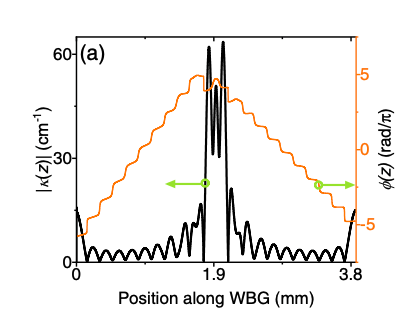
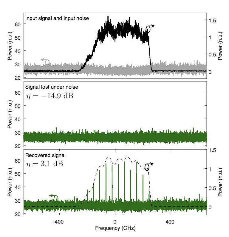
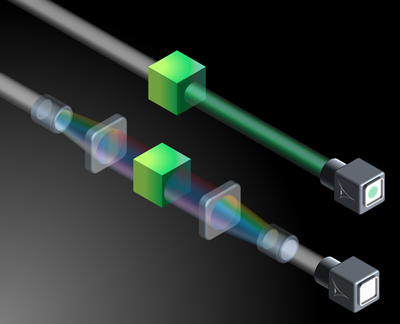
We demonstrated that it is possible to conceal the presence of an object to an observer under broadband illumination by altering the spectrum of the probe wave through reversible transformations of its temporal and spectral phase profiles. This novel approach has been referred to as spectral invisibility cloaking. In particular, the energy spectrum of the illumination wave is first redistributed towards frequency regions where the object to be concealed is transparent, and the wave is subsequently restored to its exact original shape once it has cleared the object. This way, the illumination wave can propagate through the object, entirely unaltered, while avoiding any interaction between object and wave. Our particular demonstration of this general concept made use of a set of phase transformations derived from the theory of the Talbot effect. First, the spectrum of a coherent broadband wave was redistributed into a periodic set of frequency gaps (regions of the wave’s spectrum stripped of energy) through a combination of group velocity dispersion and electro-optical phase modulation. The frequencies of such gaps were chosen to match the interaction spectrum of the object to be concealed, namely, an optical filter consisting of a periodic set of phase-shifted wide absorption bands, in the reported experiments. The spectrally-redistributed wave propagated then through the filter without interacting with it, and the applied transformations were reversed at the output of the filter, recovering both the spectral and temporal profiles of the original wave. When the cloak transformations were not applied, the action of the filter (its signature) was clearly observed in both the frequency and time domains.
We believe that the spectral invisibility concept, by virtue of preserving the full-field profile of the illumination wave, paves the way towards development of practical broadband invisibility cloaks.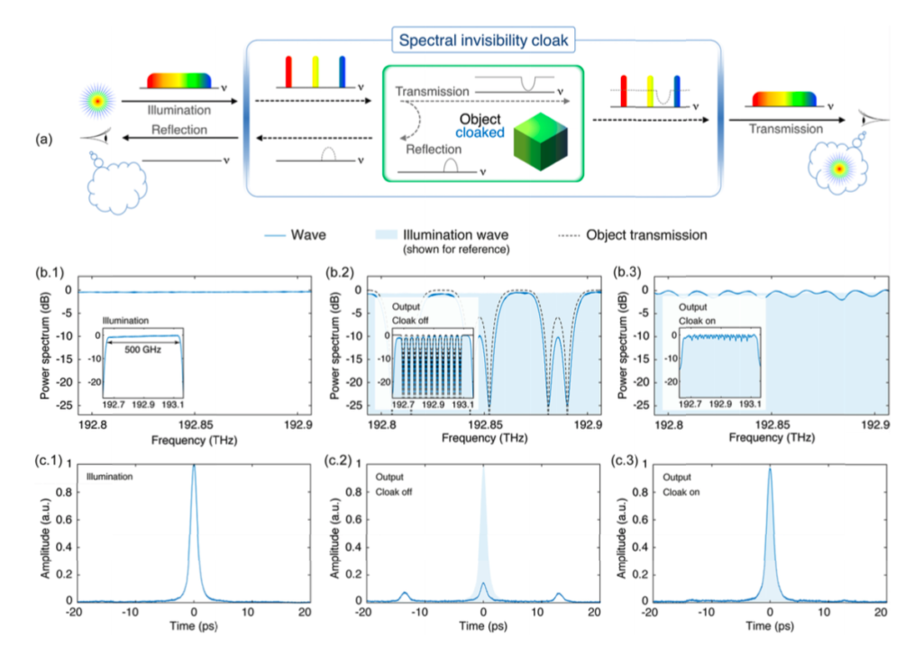
Figure: Spectral invisibility cloaking. (a) Process of concealing the signature of an object from detection by a broadband illumination wave through reversible redistribution of the wave’s frequency spectrum. (b) and (c) show experimental results (frequency spectra and temporal autocorrelation traces, respectively) of a proof-of-concept demonstration of spectral invisibility cloaking of an object (optical filter) illuminated by a short pulse of light: (1) Broadband illumination wave, (2) object’s signature when the cloak is inactive, and (3) output of the cloak, showing concealment of the object’s presence. The idea is explained with this concept video, further described by this short experiment video.
This work has attracted much attention worldwide, from news platforms such as Global news (Canada), both online and on the radio (July 5 2018, time mark 01h:02min), Lapresse (Québec), The Times (UK), El País (Spain), Radio Televisión Española (Spain), ANSA (Italy), Optics and Photonics news (USA), to name a few.

Temporal imaging and related concepts provide new, unique opportunities for generation, measurement and processing of time-domain waveforms across a wide range of frequency regimes, from electronic and radio-frequency (RF) signals to ultrafast optical information. Temporal imaging systems developed to date are based on suitable combinations of dispersive processes and time lenses, and they generally rely on coherent optics. For high performance (high time resolution over a long temporal aperture), these systems require the use of short-pulse light sources (e.g. mode-locked lasers) and precise coherent phase control of the involved waveforms. These requirements represent a fundamental hurdle to the practical use of these methods. Temporally incoherent light sources are inherently broadband and they are significantly simpler and more affordable than their coherent counterparts. We have recently proposed and experimentally demonstrated the first scheme for temporal imaging, including time-to-frequency mapping and temporal magnification or compression, of incoherent-light intensity waveforms. The scheme is based on a time-domain equivalent of a classical pinhole camera illuminated by incoherent light, and it employs only temporal intensity modulation (time-domain pinhole) combined with two dispersive lines. We have reported demonstration of incoherent-light temporal imaging of RF waveforms with a resolution of ~50 ps over a temporal aperture exceeding 8 ns, using a ~146-ps temporal pinhole. Our proposal opens up entirely new possibilities for realization of a wide variety of critical high-speed signal processing modules using simple and practical incoherent light-wave schemes.
Fig. 1 Incoherent-light temporal imaging concept (a, b) and experimental results (c, d). (a) Illustration of an incoherent-light spatial imaging system (pinhole camera) based on free-space diffraction and a pinhole. (b) Proposed scheme for incoherent-light temporal imaging, which is constructed as the temporal equivalent of the incoherent-light pinhole camera, involving temporal group-velocity dispersion and intensity modulation with a fast temporal shutter (temporal pinhole). (c) Temporal intensity profile (solid black) of the output image compared with the scaled input temporal waveform (dashed blue), where the scaling between input time and output time is the predicted magnification factor M = (±1981 ps/nm) / (±692 ps/nm)=2.86. (f) Spectrum (solid red) of the output image compared with the input temporal waveform (dashed blue), where the scaling between input time and normalized output wavelength (with respect to the signal’s central optical wavelength) is the predicted time-to-frequency mapping factor, 692 ps/nm. All profiles in (b)-(d) are averaged for 256 times.

[1] B. Li and J. Azaña, Opt. Lett. 39, 4243 (2014).
[2] B. Li, J. Azaña, “Theory of incoherent-light temporal imaging systems based on a temporal pinhole,” IEEE/OSA J. Lightwave Technol., vol. 34, pp. 2758 – 2773 (2016).

We proposed a very general concept for user-defined, arbitrary linear processing of incoming high-speed RF (microwave, millimeter-wave) signals through temporal modulation of the signal under analysis by a spectrally-shaped broadband incoherent lightwave followed by optical chromatic dispersion [1].
Such a concept is referred to as “time-spectrum convolution” and it has enabled implementation of many important functionalities on high-speed RF signals. As an example, a wide range of time-domain signal processing operations are based on the use of large amounts of group-velocity dispersion (GVD) over time-limited waveforms. Dispersion-engineering has been extensively used in the optical domain for applications such as real-time Fourier transformation (RTFT), real-time reflectometry and interferometry, pulse repetition rate multiplication, temporal imaging etc. Similar concepts have also proved extremely useful in other frequency regions, including the microwave domain. However, in the microwave domain, there is a lack of devices capable of inducing a large amount of GVD, namely above a few ns2, over a wide frequency range (0 ~ 100 GHz). Plot (A) shows an schematic of a fiber-optics incoherent-light configuration based on the time-spectrum convolution concept aimed at inducing extraordinary GVD amounts on electrical (RF) waveforms (double-pulse in the illustration) [2].
This system is capable of fulfilling the above defined stringent GVD-bandwidth requirements. In the illustrated example, a GVD equivalent to that of 185,000 km of standard single-mode fiber (SMF) is induced on the input microwave signal by propagation through a section of only 120 km of SMF. (B) Results corresponding to an example of real-time Fourier transformation (linear frequency-to-time mapping) of a nanosecond-long input microwave signal with a full bandwidth approaching 20 GHz (input signal shown in the top plot). The bottom plot shows the measured output temporal waveform (blue curve, bottom axis) as compared with the signal input spectrum (green curve, top axis). Temporal differentiation and integration of high-speed microwave signals have been also demonstrated by our group based on the same time-spectrum convolution concept (see for instance Ref. [3] below)
[1] Y. Park, J. Azaña, “Optical signal processors based on time-spectrum convolution process,” Opt. Lett., vol. 35, pp. 796-798 (2010).
[2] Y. Park, J. Azaña, “Ultrahigh dispersion of broadband microwave signals by incoherent photonic processing,” Opt. Express, vol. 18, pp. 14752-14761 (2010).
[3] A. Malacarne, R. Ashrafi, M. Li, S. LaRochelle, J. Yao, J. Azaña, “Single-shot photonic time-intensity integration based on a time-spectrum convolution system,” Opt. Lett., vol. 37, pp. 1355-1357 (2012).

Optical pulse shaping (OPS) refers to the capability of re-shaping the temporal variation of a given input ultra-short optical pulse into a target, desired waveform shape. Picosecond-resolution OPS is desired for many important applications, particularly in the context of ultrahigh-bit-rate optical fiber communications and ultrafast optical signal processing.
We have recently developed a new approach for picosecond OPS on a silicon chip, overcoming critical challenges of previous approaches [1-3]. Our approach, referred to as discrete space-to-time mapping (STM), is based on the use of cascaded co-directional couplers in silicon-on-insulator technology, and it exploits the fact that the ‘discrete’ amplitude and phase ‘apodization’ profile of the concatenated couplers (coupling coefficient and phase deviation between parallel waveguides in the coupler) can be directly mapped into the output temporal response of the device, as long as the structure is designed to operate under weak-coupling conditions. The proposed design is based on forward coupling between a main waveguide and a bus waveguide, where the coupling is controlled in a discrete fashion through standard co-directional couplers. Recall that a standard co-directional coupler is a 4-port device, consisting of four S-bends and two identical waveguides which are parallel to each other at the coupling region. In practice, the vertical spacing between these waveguides (coupling gap) or their length (coupling length) could be tuned to achieve different coupling ratios. Besides, the phase could be tuned by adjusting the relative waveguide length (optical path length) difference between the bus- and main-waveguides connecting the upper and lower ports of consecutive couplers, respectively.
The resulting devices are notably simpler to fabricate than previously proposed integrated-waveguide OPS schemes, while potentially enabling reconfigurability through well-established mechanisms. For instance, thermo- or electro- optical effect could be implemented to design electrically-tunable variable optical attenuators, and phase-shifters to actively control the coupling strength and relative phase at each stage of the device, respectively. Through the use of our proposed technique, we have managed to generate optical pulses with sub-picosecond temporal resolutions and durations ranging from few picoseconds up to tens of picoseconds. Discrete-STM has been also used for generation of ultra-fast (Tbit/s) complex modulated bit-packets.

[1] H. P. Bazargani, J. Azaña, “Optical pulse shaping based on discrete space-to-time mapping in cascaded co-directional couplers,” Opt. Express, vol. 23, no. 18, pp. 23450-23461 (2015).
[2] H. P. Bazargani, M. Burla, J. Azaña, “Experimental demonstration of sub-picosecond optical pulse shaping in silicon based on discrete space-to-time mapping,” Opt. Lett, vol. 40, no. 23, pp. 5423-5426 (2015).
[3] H. P. Bazargani, M. Burla, Z. Chen, J. Zhang, L. Chrostowski and J. Azaña, “Long-duration optical pulse shaping and complex coding in SOI using discrete space-to-time mapping,” IEEE Photon. J., vol. 8, no. 4, pp. 1-7 (2016).

Reconfigurable optical pulse shapers have been successfully demonstrated with resolutions well into the sub-picosecond range by processing the input time-domain pulse waveforms along the spatial domain, e.g., using programmable spatial light modulators (SLMs). However, this approach requires the use of for efficient coupling between fiber and free-space optics and multiple spatially-separated modulation points, which translate into a relatively lossy and bulky configuration. The approach is also constrained by the relatively limited update rate of SLMs, typically below the kHz range.
Alternatively, time-domain optical pulse shapers, where the filtering function is programmed directly in the time domain using a single high-speed electro-optic modulator (EO-M), have attracted a great deal of attention due to their all-fiber simple configuration, capability to achieve high-speed pulse-shape update rates, into the sub-GHz range, and solid potential for integration [1]. However, all previously demonstrated schemes for time-domain pulse shaping were limited to synthesizing purely symmetric temporal intensity waveforms; arbitrary, asymmetric picosecond optical waveforms are needed for many important applications, including nonlinear wavelength conversion, time-division add–drop multiplexing, etc.
In a recent work, we experimentally demonstrated a fiber-optic programmable picosecond pulse shaper using multi-level phase-only linear filtering in the time-domain [2]. The demonstrated shaper enables the synthesis of high-quality, fully arbitrary (including asymmetric) temporal intensity profiles. The schematic of the time-domain pulse shaping system is shown in Fig. 1. In order to implement the computed spectral filtering of the pulse’s phase profile, the input pulse’s frequency components are first linearly distributed along the time domain by linear propagation through a second-order dispersive medium. The temporally stretched pulse is then phase-modulated by using an EO-phase modulator (PM) driven by a time-domain modulation signal that maps the desired phase spectral-transfer function. The needed spectral phase filtering function is obtained through a combined Gerchberg-Saxton algorithm and genetic algorithm. By subsequently compressing the stretched, phase-modulated pulse with a dispersion compensator, the target temporal intensity profile can be directly obtained at the system output.

As examples, we report here the synthesis of asymmetric triangular pulse shapes, and high-speed (~150 Gbaud) random on-off-keying (OOK) pulse and pulse-amplitude-modulation (PAM) code sequences, with a resolution of ~2 ps over a maximum temporal window of ~60 ps, corresponding to an estimated frequency resolution of ~16 GHz. φ2 stands for optical second-order (group-velocity) dispersion.

[1] S. Thomas, A. Malacarne, F. Fresi, L. Potì, A. Bogoni, J. Azaña, “Fiber-based programmable picosecond arbitrary optical pulse shaper,” IEEE/OSA J. Lightwave Technol., vol. 28, pp. 1832-1843 (2010).
[2] J. Huh, J. Azaña, “In-fiber reconfigurable generation of arbitrary (asymmetric) picosecond temporal intensity waveforms by time-domain optical pulse shaping,” Opt Lett, vol. 41, pp. 693-696 (2016).
•Application of the developed optical waveform processing/shaping techniques for ultrafast optical clock generation, manipulation and recovery, ultrahigh-bit-rate optical switching, classical (analog) and quantum computing, nonlinear/quantum optics studies, and real-time characterization of complex, low-power ultrafast optical waveforms.

Fiber-optics picosecond optical pulse lasers have become an essential tool for fundamental science and practical applications. However, present mode-locking technologies offer limited capabilities to tune a key laser specification, namely the pulse repetition-rate, which is additionally constrained by electronics up to a few tens of GHz. Such limitations are critical for applications in high-speed telecommunications, ultrafast computing, optical and radio-frequency waveform generation and processing etc. One attractive methodology to generate picosecond optical pulse trains, with rates beyond those achievable by mode-locking, is to multiply the repetition rate of the original source outside the laser cavity using so-called all-optical pulse repetition-rate multiplication (PRRM) techniques. In particular, PRRM based on temporal self-imaging (TSI) or Talbot effect has attracted a great deal of attention over the years (see for instance pioneering work in IEEE J. Sel. Topics Quantum Electron. 7, 728(2001)).
This technique simply requires propagation of the original pulse train through a transparent, highly-dispersive optical medium. However, conventional TSI-based PRRM techniques employ either a fixed length of dispersive fiber or a chirped fiber Bragg grating to achieve a prescribed, fixed rate-multiplication factor, so that reconfigurability of the rate-multiplication factor is not possible without changing the dispersive medium itself. We have recently proposed and experimentally demonstrated a strikingly simple fiber-optics approach for PRRM where the repetition-rate multiplication factor can be programmed electronically. This PRRM method exploits TSI in an entirely new fashion, involving the use of a fiber-integrated electro-optic temporal phase modulator preceding a dispersive line. The key feature of this system is that the dispersive line is fixed and the rate-multiplication factor (m) can be programmed simply by modifying the electronic phase modulation profile. The figure below summarizes results on one of our experiments demonstrating programmable undistorted PRRM of a 9.7 GHz mode-locked fiber laser by factors ranging from m=1 (output repetition rate of 9.7 GHz) to m=4 (output repetition rate of 38.8 GHz).The technique has been recently extended to achieve programmable lossless pulse repetition rate division (leading to individual pulse amplification)
Fig. 1 (a) Programmable repetition-rate multiplication concept: a low-rate input optical pulses with temporal repetition period of T (i.e., repetition-rate of f=1/T) is first phase-modulated along the time domain by an electro-optic phase modulator and subsequently propagated through a dispersive medium, whose dispersion coefficient is fixed to satisfy the integer Talbot condition (φ2=T2/2π)
. The multiplication factor, m, is electrically tuneable and depends only on the temporal phase modulation profile function (ϑn=[(m-1)/m] π n2, where n=0,1,2,…,m-1). (b, c) Experimental results. (b) The prescribed phase modulation profiles applied to the input 9.7 GHz optical pulses, for multiplication factors of m=1 to 4, respectively. The actual phase drive is delivered by an arbitrary waveform generator. (c) The temporal intensity waveforms of the resultant multiplied pulse trains after dispersion of D2=1325 ps/nm. The inset shows the superposition of input and multiplied output
normalized individual pulses, confirming generation of nearly undistorted copies of the input pulses.

[1] R. Maram et al. J. Lightwave Technol. 34, 5403 (2016).
[2] R. Maram et al. Optical Fiber Communication Conference, Anaheim, USA(2016). Invited paper W3E.4.
[3] R. Maram, L. Romero Cortes, J. Van Howe, J. Azaña. (2017). Energy-preserving arbitrary repetition-rate control of periodic pulse trains using temporal Talbot effects IEEE/OSA Journal of Lightwave Technology. 35(4): 658 – 668.
[4] J. Jeon, R. Maram, J. van Howe, J. Azaña. (2018). Programmable passive Talbot optical waveform amplifier. Optics Express. 26(6): 6872-6879.

Dynamic identification of instantaneous microwave or mm-wave frequencies is a critical functionality in widespread applications such as broadband communications, biomedical instrumentation, electronic countermeasures, radar and more. Photonics solutions have demonstrated the potential to overcome the lack of flexibility and severe bandwidth limitations of current electronic instantaneous frequency measurement (IFM) systems. However, they suffer from at least one of the following critical problems: they are either implemented using costly, bulky discrete components, and/or they are based on nonlinear-optics processes, requiring high optical powers for operation. These limitations represent a fundamental hurdle towards the use of photonic-based IFM systems in practical, real-world applications.
In a recent demonstration, we used a simple integrated optical waveguide Bragg grating (WBG) filter on silicon, approximately 65 µm long (Fig. 1, left), to implement an ultra-compact, fully linear IFM system. The operating principle uses the WBG transmission (TX) and reflection (RX) responses that, over a certain frequency region, display opposite slope versus frequency (Fig. 1, right). Those opposite slopes are used to create an RF-frequency discriminator as shown in Fig. 2. The RF signal whose frequency is to be identified modulates an optical carrier; the single-sideband modulated signal enters the WBG; the transmission (TX) and reflection (RX) outputs of the WBG enter two equal photodetectors (PDs); the PDs output power ratio defines the amplitude comparison function (ACF), which shows an increasing value versus frequency and can be used as a frequency discriminator.
The device in Fig. 1 provides 3 orders of magnitude more compactness (tens of microns vs. millimeters or even centimeters) and the system requires 10 times less optical power (down to ~10 mW) than previously reported on-chip photonic-based IFM systems, and is capable of operation over a bandwidth beyond 30 GHz. The measurement accuracy offered by this platform reaches 0.026%, comparable to systems employing km-long optical fibers, but with the potential of 5 orders of magnitude less latency (tens of picoseconds).
We also demonstrated that the system can successfully identify a frequency-varying microwave signal in a dynamic fashion, i.e. identifying not only the frequency components of an incoming unknown microwave signal but also their instantaneous location in time, without any need for a fast oscilloscope or a high-frequency spectrum analyzer. In particular, we showed how the reported photonic IFM platform enables dynamic identification of instantaneous frequencies well above 10 GHz using simple, widely accessible electronic circuits with detection/measurement bandwidths in the sub-GHz range and below (Fig. 3).

Figure 1 | Silicon WBG and optical responses. Left: (a) Schematic of the silicon WBG (PS-WBG) employed as a linear-optics frequency discriminator. TX port, transmission port; RX port, reflection port. (b) Scanning electron microscope (SEM) image of the strip waveguide with sidewall corrugations (scale bar, 500 nm). (c) Y-branch used to access the reflection port of the PS-WBG. Right: simulated (dashed line) and measured (solid line; a) linear optical transmission and (b) reflection spectral responses of the PS-WBG; (c,d) zoom with overlapped OSSB+C spectrum. The optical responses are normalized to the maximum.
Figure 2 | IFM system set-up and RF responses. Left: schematic of the experimental set-up of the IFM system, including continuous-wave laser (CW), polarization maintaining fibre (PM), polarization controller (PC), dual-parallel Mach-Zehnder modulator (DP-MZM), erbium-oped fibre amplifier (EDFA), phase-shifted waveguide Bragg grating (PS-WBG) and photodetector (PD). RX, reflection port; TX, transmission port. Right: RF response of TX and RX ports; Amplitude comparison function (ACF).
Figure 3 | Experiment of dynamic frequency identification. (a) An RF signal with unknown frequency content enters the photonic IFM system in Fig. 3. (b) The time-domain signal at the IFM output is amplitude-coded according to the time-varying frequency content of the input signal. (c) The instantaneous power is extracted by self-mixing and low-pass filtering. (d) Using the inverse ACF, the RF frequency content is estimated in a dynamic manner. (e) The spectrogram of the frequency-hopping input sequence is shown for comparison. (f–j) Input sequence with frequency components at 2.4–6–12–4.8 GHz: (f) input waveform; (g) waveform processed by the IFM system, (h) average power extracted by mixing and low pass filtering, (i) estimated instantaneous frequency, (j) calculated spectrogram of the input sequence, shown for comparison to the estimated frequency in (i).
[1] Burla, M., Wang, X., Li, M., Chrostowski, L. & Azaña, J. Wideband dynamic microwave frequency identification system using a low-power ultracompact silicon photonic chip. Nat. Commun. 7, 13004 doi: 10.1038/ncomms13004 (2016).
[2] L. Romero Cortés*, D. Onori*, H. Guillet de Chatellus, M. Burla, J. Azaña. (2020). Towards on-chip photonic-assisted radio-frequency spectrum measurement and monitoring (INVITED). Optica. 7(5): 434-447.
Research Funding
The conducted research in the group has been possible thanks to generous financial support and grants from research funding agencies, including the Canada Research Chairs Program of the Government of Canada, the Natural Science and Engineering Research Council of Canada (NSERC), the Fonds de Recherche de Quebec en Nature et Technologies (FRQ-NT), the Canadian Foundation for Innovation (CFI), etc., and private industrial partners, including Fonex, Huawei-Canada, MPB, O/E Land, Aeponyx, QPS Photronics, Apollo Microwaves, Exfo etc. Among other initiatives, the group has led 7 Strategic Research Projects (2 ongoing), the flagship research partnership program of NSERC.


![]()